HOW TO
Georeference multiple CAD data in ArcGIS Pro
Summary
Georeferencing CAD data is the process of spatially adjusting a CAD drawing by linking points to known geographic coordinates. In some instances, multiple CAD data must be georeferenced by applying the same control points in ArcGIS Pro. This article provides the workflow to georeference multiple CAD data simultaneously using the same transformation in ArcGIS Pro.
Procedure
Note:
All CAD data must be stored in the same folder.
- In an ArcGIS Pro new project, set the projection of the map to be the same as the CAD data to georeference.
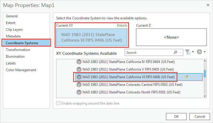
- In the Contents pane, right-click the map, and click Properties.
- In the Map Properties window, click Coordinate Systems, select a coordinate system, and click OK.
- Add one of the CAD data (.dwg) to the map, and define the projection of the data.
- On the Map tab, in the Layer group, click Add Data
 .
. - Navigate to and select the required CAD data, and click OK.
- In the Contents pane, click a layer of the CAD data.
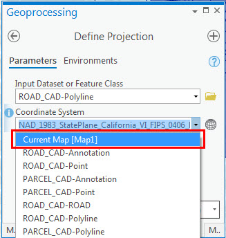
- On the CAD Layer tab, in the Alignment group, click Define Projection
 .
.
- On the Map tab, in the Layer group, click Add Data
Note:
The CAD Layer tab is not visible when a CAD group layer is selected. To display the tab, select a child feature layer in the CAD group layer.
- In the Define Projection window, for Coordinate System, select Current Map, and click Run.
- Georeference the CAD data. Click Save to apply the transformation and save the georeferencing control points to an auxiliary world (.wld) file in the CAD workspace. Refer to Georeference CAD data for more information.
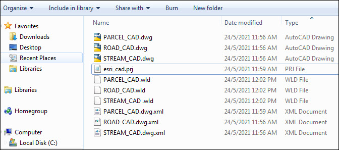
- Navigate to the folder containing all the CAD data, and rename the projection (.prj) file to esri_cad.prj.
- Copy and paste the auxiliary world (.wld) file created in Step 3 within the same folder, and rename it to the name of other CAD data. Repeat this step depending on the number of CAD data (.dwg) that exist in the folder. In this example, there are three different .wld files with the same name as the three .dwg files (PARCEL_CAD, ROAD_CAD, and STREAM_CAD).
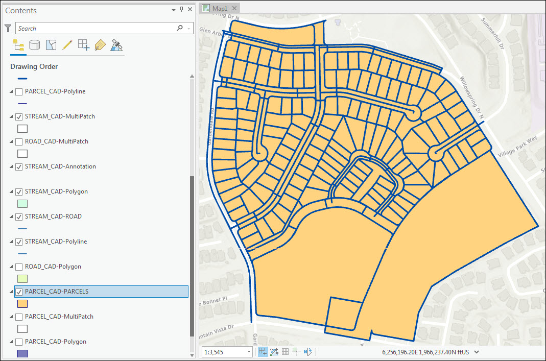
- In ArcGIS Pro, add all the CAD data simultaneously. The CAD data are georeferenced and located at their respective locations.
The image below shows multiple georeferenced CAD data in ArcGIS Pro using similar control points and transformation.
Article ID: 000025645
- ArcGIS Pro 2 8 x
- ArcGIS Pro 2 7 x
- ArcGIS Pro 2 x
Get support with AI
Resolve your issue quickly with the Esri Support AI Chatbot.


Related Information
Discover more on this topic
Search for related information
Find training related to this topic
Explore ideas and give feedback
Get help from ArcGIS experts
Start chatting now