HOW TO
Convert PNG to vector features in ArcGIS Pro
Summary
In ArcGIS Pro, a PNG layer is a non-spatial raster image, often used for visual reference, digitizing, or overlaying graphics. As PNGs do not inherently store geographic coordinates or projection information, they must be georeferenced before they can be used in spatial workflows. PNGs allow tracing of features, can provide context or be converted into vector data for further analysis.
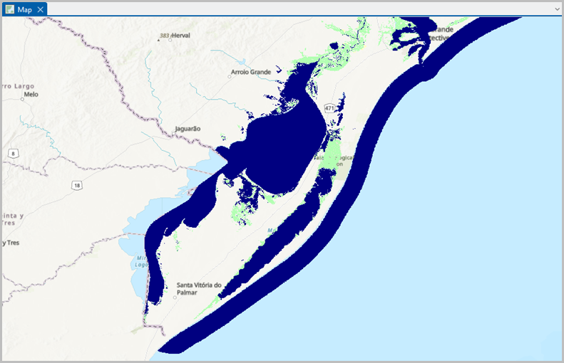
The map below demonstrates the PNG layer before it is converted into vector features and this article provides the workflow.
Procedure
Note:
This workflow is designed for PNG images that represent distinct line features rather than continuous imagery.
- Open the ArcGIS Pro project and add the PNG file to the map.
- Run the Raster To Polygon tool to convert the PNG image to a polygon.
- On the Analysis ribbon tab, in the Geoprocessing group, click Tools.
- In the Geoprocessing pane, search for and select Raster To Polygon (Conversion Tools).
- In the Raster To Polygon pane, for Input raster, click the drop-down arrow and select the PNG layer.
- For Field, click the drop-down arrow and select Value.
- Specify a name for Output polygon features.
- Uncheck the Simplify polygons check box and click Run.
- Convert the polygon boundaries into line features using the Feature To Line geoprocessing tool. Refer to ArcGIS Pro: Feature To Line (Data Management) for more information.
- On the Geoprocessing tab, click the Back button to return to the Geoprocessing pane.
- In the Geoprocessing pane, search for and select Feature To Line (Data Management Tools).
- In the Feature To Line geoprocessing pane, for Input Features, click the drop-down arrow and select the output from Step 2.
- For Output Feature Class, specify the location.
- Click Run.
- Reproject the spatial reference using the Project tool. Refer to ArcGIS Pro: Project (Data Management) for more information.
- On the Geoprocessing tab, click Back to return to the Geoprocessing pane.
- In the Geoprocessing pane, search for and select Project (Data Management Tools).
- In the Project geoprocessing pane, for Input Dataset or Feature Class, click the drop-down arrow and select the output from Step 3.
- For Input Coordinate System, click the drop-down arrow and click Current Map [Map].
- For Output Dataset or Feature Class, specify a name for the output.
- For Output Coordinate System, click the drop-down arrow and click Current Map [Map].
- In the Geographic Transformation section, click the drop-down arrow next to the suggested transformation to view the geographic transformation list, and select a transformation.
- Click Run.
- Break the continuous loops into smaller line segments using the Split Line At Vertices geoprocessing tool.
- On the Geoprocessing tab, click the Back button to return to the Geoprocessing pane.
- In the Geoprocessing pane, search for and select Split Line At Vertices (Data Management Tools).
- In the Split Line At Vertices pane, for Input Features, click the drop-down arrow and select the output from Step 4.
- For Output Feature Class, specify the location.
- Click Run.
- Generate a single centerline using the Collapse Dual Lines To Centerline tool. Refer to ArcGIS Pro: Collapse Dual Lines To Centerline (Cartography) for more information.
- On the Geoprocessing tab, click Back to return to the Geoprocessing pane.
- In the Geoprocessing pane, search for and select Collapse Dual Lines To Centerline (Cartography Tools).
- In the Collapse Dual Lines To Centerline pane, for Input Features, click the drop-down arrow and select the output from Step 5.
- For Output Feature Class, specify the location.
- For Maximum Width and Minimum Width, specify the desired measurement.
- Click Run.
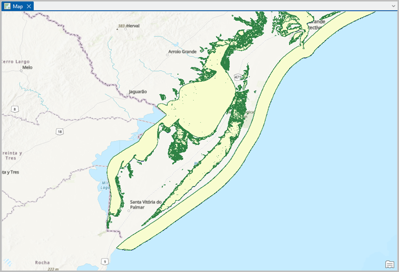
The map below shows the resulting vector features from the converted PNG layer.
Article ID: 000039412
- ArcGIS Pro
Get support with AI
Resolve your issue quickly with the Esri Support AI Chatbot.


Related Information
Discover more on this topic
Search for related information
Find training related to this topic
Explore ideas and give feedback
Get help from ArcGIS experts
Start chatting now