方法
重複しているポイント フィーチャ シンボルをオフセットする
サマリー
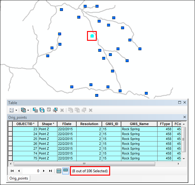
When working with a feature class containing overlapping point features with identical locations, it may be desired to individually display the many overlapping points. For example, the following image shows one point feature symbol selected but there are actually eight overlapping point features in that location, as displayed in the attribute table.
手順
ArcMap can be used to offset the overlapping point feature symbols. The first option uses Maplex Label Engine to create labels for all point features and displaces the labels of the overlapping features. The other option uses the Disperse Markers tool to scatter the point feature symbols.
Using the Maplex Label Engine
This method labels the point features with a symbol rather than applying symbology to the layer. The Maplex Label Engine places the first label on its point’s location and displaces subsequent labels for the overlapping point features.
Note:
This method is recommended for layers containing fewer than 10 overlapping point features at one location. In some cases, the Maplex Label Engine is unable to display all overlapping point features on the map due to the labeling settings.
- Set the point layer symbology color to 'no color'. If the layer uses a simple marker symbol, turn off the outlines by unchecking the Use Outline option. Or, uncheck the layer to turn off the drawing of the symbol.
- Double-click the point layer in Table Of Contents to open the Layer Properties dialog box.
- Click the Symbology tab.
- Click the Symbol button to open the Symbol Selector dialog box, change the Color to No Color, and set the Size to 1.
- If required, click Edit Symbol to open the Symbol Property Editor dialog box, and uncheck the Use Outline option.
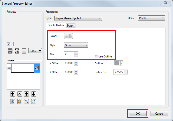
- Click OK in all dialog boxes to apply the symbology settings.
- Enable labeling for the point layer. Right-click the layer and select Label Features.
- Add the Labeling toolbar, and enable the Maplex Label Engine. Refer to Exercise 1: Enabling the Maplex Label Engine and adding the Labeling toolbar for steps to do this.
- Use the Maplex Label Engine to create labels for the point features in the Label Manager.
- Under the Text Symbol section in the Label Manager dialog box, click Symbol.
- In the Symbol Selector dialog box, click Edit Symbol.
- Set a marker text background to label the features with a desired symbol. Refer to the following document for steps to create labels with a marker text background: Text inside highway shields or other markers, and click Symbol to select the desired symbol.
- Click OK in all the dialog boxes to return to the Label Manager dialog box.
- Set the labels placement to avoid stacking labels and adjust the labels location.
- In the Placement Properties section, uncheck Stack label, and click Properties.
- Set the label position and select the Best Position placement option.
- Set the label offset and enter the preferred offset value to control the distance between a label and its feature.
- Specify a label buffer distance to change the space between labels. This allows the labels to be placed in close proximity, freeing up space for more labels to be placed.
- Click OK to close all the dialog boxes and to apply the label settings.
The following image shows the dispersed labels of the point features by applying the Maplex Label Engine.
Note:
The Offset value in the Label Manager window may need to be increased for all points to become visible.
Using the Disperse Markers tool
This method displays all the overlapping point features without changing the original point feature coordinates. The Disperse Markers tool finds overlapping representation markers and spreads them based on a minimum spacing and dispersal pattern.
Note:
This workflow requires the ArcGIS Desktop Advanced license.
- Convert the symbology of the feature class to representation. Refer to Creating representations for steps to do this.
- Use the Disperse Markers tool to scatter the point feature symbols.
- In ArcToolbox, navigate to Cartography Tools > Cartographic Refinement > Disperse Markers.
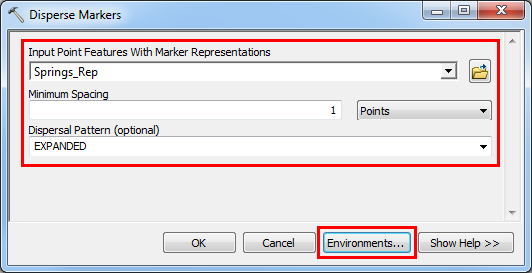
- In the Disperse Markers dialog box, specify the parameters, and click Environments.
- In the Environment Settings dialog box, expand the Cartography settings.
- Input a value for the Reference Scale to define the scale at which symbols appear in the intended size. For example, insert 10,000 to display symbols at the intended size when the map is zoomed to the scale of 1:10,000.
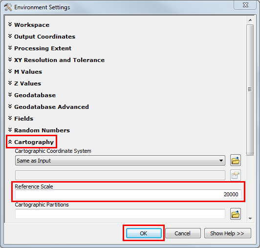
- Click OK to close the Environment Settings dialog box.
- Click OK in the Disperse Markers dialog box to run the tool.
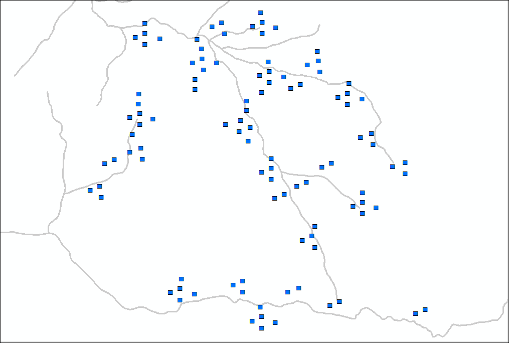
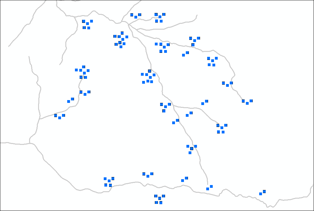
The following image shows the dispersed point feature symbols using the Disperse Markers tool.
記事 ID:000018638
ArcGIS の専門家からヘルプを受ける
Esri Support アプリのダウンロード
関連情報
このトピックについてさらに調べる
Search for related information
Find training related to this topic
Explore ideas and give feedback