CÓMO
Utilizar puntos de control del terreno en Site Scan Manager for ArcGIS
Resumen
Instructions provided describe how to use ground control points (GCPs) in the Site Scan Manager for ArcGIS web application.
Causa
When collecting drone imagery, it is often helpful to use ground control points (GCPs) to ensure the image collection has high accuracy. Given the extremely small pixels of drone imagery, highly accurate GCPs may be required, depending on the project. Using a real-time kinematic positioning (RTK) GPS unit to create GCPs is a best practice to collect geographically accurate drone imagery. This how-to guide demonstrates the process for adding RTK GCPs to Site Scan Manager.
Procedimiento
Collect ground control points
- Set the ground control points using an RTK unit and identifiable markers.
- Follow the instructions described in the article: How To: Set ground control points for use in Site Scan for ArcGIS.
The project surveyor may also provide the ground control points.
Upload ground control points to Site Scan Manager
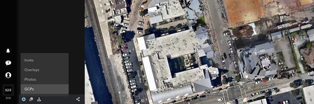
- Click the plus sign (+) button on the bottom toolbar and select GCPs.
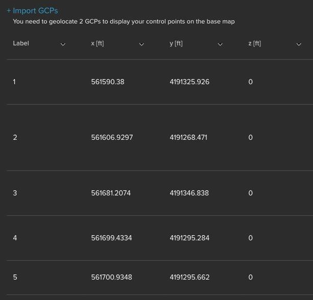
- Drag and drop a .csv or .txt file with the GCPs, or click the + Import GCPs button and locate the file. This must only be done once for each project, unless there are additional GCPs collected at a later date.
Select a known or custom coordinate system
By default, WGS 84 is selected, but an EPSG code can be entered to find a coordinate system, or choose to use a custom coordinate system.
- Confirm columns are correct. The GCP tool expects coordinates to be in x, y, z order. If the coordinates are y, x, z, a warning is returned.
- Change the order using the drop-down at the top of the columns.
If using a custom coordinate system
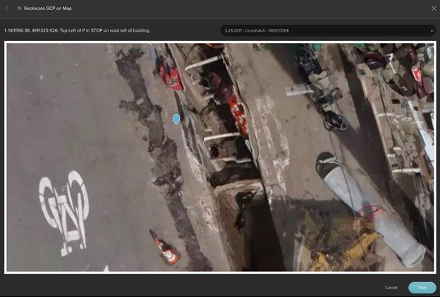
- After inserting the control points, a new column displays, called Geolocate on Map. Choose a control point row, and click the Geolocate on Map link in that row.
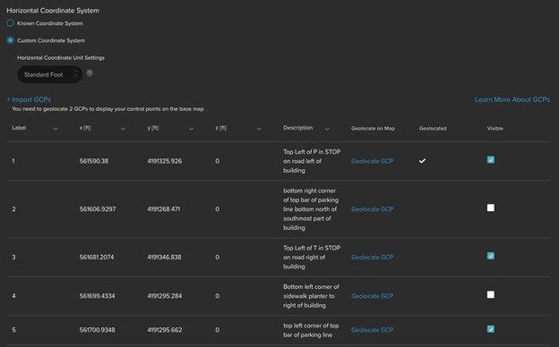
- A view of the orthomosaic displays. Use the orthomoasic to locate the control point and click it.
- Repeat this process for a second control point.
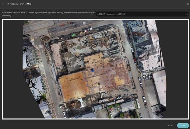
This process is used to place the GCPs over the orthomosaic to choose the right photos for the control point.
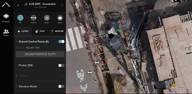
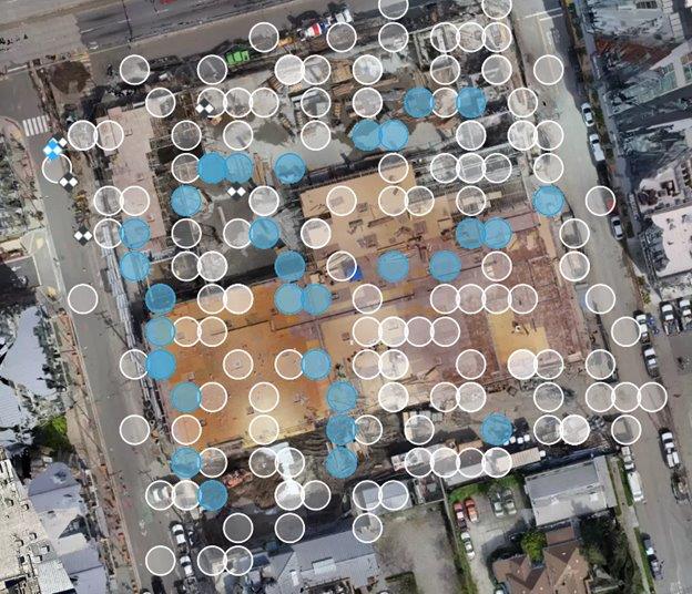
Tag points in photos – smart GCPs
- After uploading the GCPs, turn on the Ground Control Points toggle and click Georeference GCPS on the toolbar.
- Click the GCP (circle with X) to tag in photos. The GCP’s border and X turn blue, and places that potentially contain control point marks are also marked in light blue on the photos.
- Select the photo to tag the GCP in. A pop-up with the photo displays. Zoom and pan to find the GCP. For best results, tag the pixel in the middle of the GCP.
- Click Save once the middle of the GCP is selected.
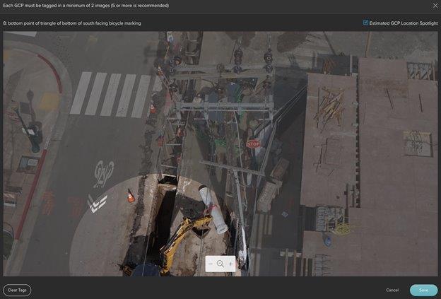
- Repeat this process until the GCP is completely blue, which required four photos in this example. Fewer photos can be processed per GCP, but more is better.
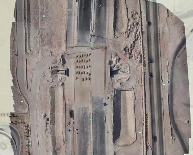
Use checkpoints (optional)
After tagging the photos to the GCPs, it may be desirable to use some control points as checkpoints. Checkpoints are not used to enhance the accuracy of the output, but to independently measure the accuracy of the results by comparing the surveyed location of the control points to their location in the processed outputs.
Note:
- Checkpoints must only be used if there are at least five other points available for use as GCPs.
- Checkpoints must be inside the site boundaries, and not on the corners.
- To obtain the most conservative accuracy values, place checkpoints as far from GCPs as possible.
- After validating accuracy with checkpoints, reprocess the flight using all points as GCPs to further enhance accuracy.
The image below shows an ideal ground control and checkpoint layout on a 40-acre site, using eight GCPs and five checkpoints. GCPs are displayed in green, and checkpoints in red.
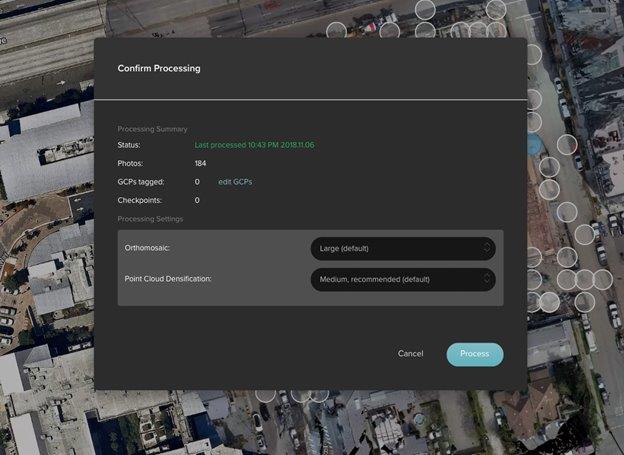
Confirm and process
Begin processing after tagging at least two GCPs each in two photos. For best results, Esri recommends tagging at least five GCPs in four to five photos each. Click the Process button to process with GCPs.
Analyze and export
With georeferenced orthomosaics, Site Scan for ArcGIS Manager’s analysis tools become even more powerful. The Overlay, Compare Flights, and Measurements tools benefit from the improved accuracy of georeferencing. Additionally, the orthomosiacs, DEMs, and point clouds (.las) are georeferenced in the desired coordinate system.
Id. de artículo:000023040
Obtener ayuda de expertos en ArcGIS
Descargar la aplicación de soporte de Esri
Información relacionada
Descubrir más sobre este tema
Search for related information
Find training related to this topic
Explore ideas and give feedback