HOW TO
Identify the auto-adjusted gaps between polygon features during topology validations
Summary
When a new topology is created or the features in a topology are edited, the topology must be validated to identify any changes within the feature that violates topology rules. Areas that violate any of the topology rules are flagged as an error and logged in the Error Inspector. For example, when a Must Not Have Gaps rule is defined on a parcel feature class and there is a sliver of open space between two parcels a topology error is presented. The width of the gap and the size of the cluster tolerance determines if the error is fixed automatically, or logged in the Error Inspector.
If the gap is larger than the cluster tolerance, the area is identified as an error. This portion of data is not changed during the topology validation, and the errors must be fixed manually. For more information on how to fix topology errors, refer to Fixing topology errors.
If the gap between features is smaller than the cluster tolerance, the gap is auto-adjusted by cracking and clustering the two boundaries between features to become one feature or to be made coincident during validation. This portion of data is changed automatically.
To determine small errors in the dataset that can be prevented in the future, the auto-adjusted gaps after topology validation must be identified. In such cases, the Feature Compare tool can be used to identify the gaps.
Procedure
The instructions provided describe the steps to identify auto-adjusted gaps between features.- In ArcMap, copy and paste the feature class into the target file geodatabase.
- Create a topology for the copy of the feature dataset with the Must Not Have Gaps rule.
- In the Catalog window, right-click the feature dataset > New > Topology.
- Specify the name and cluster tolerance, and click Next.
- Select the feature class that participates in the topology, specify the feature class rank, and click Next.
- Click Add Rule, select the parcel features class, select the Must Not Have Gaps rule, and click OK.
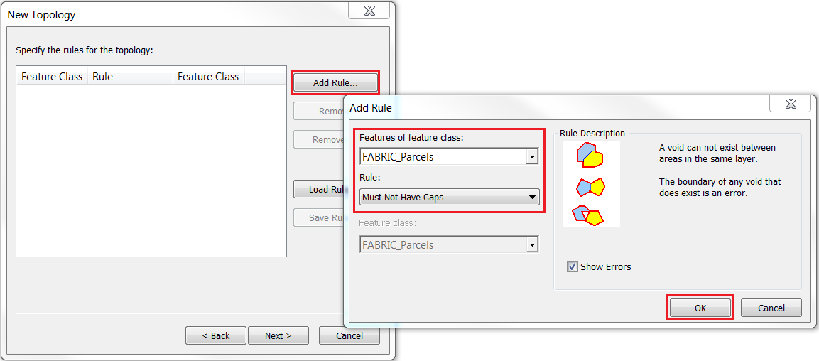
- Click Next > Finish.
- Click Yes when the validate topology dialog box appears.
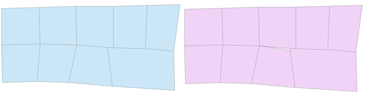
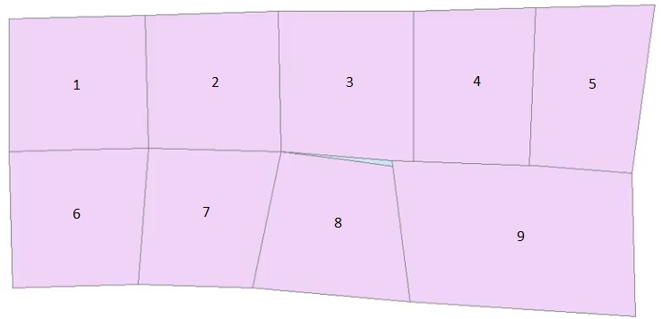
- To compare the geometry in the figure above between the validated feature class (left) and the original feature class (right), use the Feature Compare tool.
- In the Table of Contents, select the original feature class and the validated feature class, and run the Feature Compare tool.
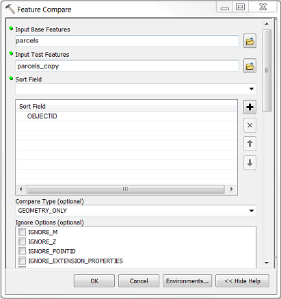
- In the Feature Compare window, select the original feature class for Input Base Features and the validated feature dataset for Input Test Features.
- Select OBJECTID for Sort Field and GEOMETRY_ONLY for Compare Type.
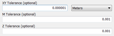
- Specify the desired xy-tolerance, m-tolerance, and z-tolerance.
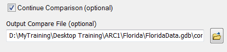
- Enable Continue Comparison to continue comparing the remaining feature properties after encountering the first mismatch.
- Select a location for the Output Compare File, and click OK to run the tool. Click Close in the Completed dialog box.
- Select and drag the comparison table from the Catalog window to the map.
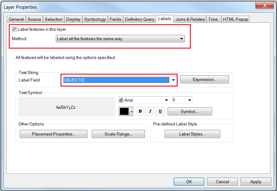
- Right-click the original feature class in the Table Of Contents > Properties > Labels.
- In the Layer Properties window, enable Label features in this layer, select Label all the features the same way for the Method drop-down list and OBJECTID for the Label Field drop-down list. Click Apply > OK. Note the ObjectID labels on all the features.
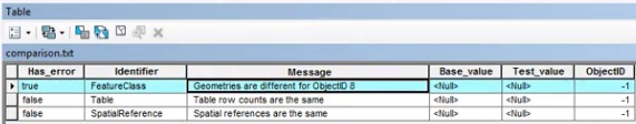
- Right-click the comparison table in the Table Of Contents, and click Open. Note the geometry difference between the two feature classes identified in the table.
Note:
To remove gaps from the feature class, refer to the following ArcGIS Web Help page: Removing slivers or gaps between polygons.
Article ID:000015344
- ArcMap
Get help from ArcGIS experts
Download the Esri Support App
Related Information
Discover more on this topic
Search for related information
Find training related to this topic
Explore ideas and give feedback