HOW TO
Understand error attributes in a dirty areas table for a utility network
Summary
What is a dirty area?
Dirty areas in a network, track edits that require validation or correction, indicating changes not yet reflected in the network's structure. They are cleared upon validating the network topology if no errors are found within the validation scope. When network topology is active, dirty areas are crucial for tracking various edits such as feature creation, attribute field modifications, and association establishment or modification. Error dirty areas are specifically generated during enable, validate, and update subnetwork operations when a utility network feature violates predefined rules and constraints.
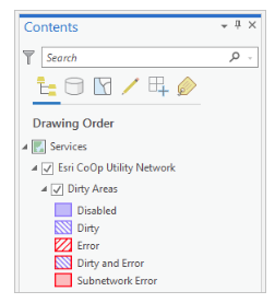
Dirty areas could be accessed as sublayer of our utility network and could be symbolized using the symbology tools. Dirty areas sublayer is symbolized using a bit-encoded value in the Status field to indicate how it was created.
What are error features?
Errors in a utility network occur when a network feature violates set rules. Upon detection, a dirty area is created around the feature. To rectify errors, edits can be made to the feature's geometry, attributes, rules, or subnetwork definition. During the next network topology validation, features with errors are reviewed. To access errors, the utility network layer must be present in the Contents pane. If it is not, add it to your active map from the Catalog pane.
Understanding error attributes
The attribute fields within the dirty areas table are utilized to identify and address errors through pop-up expressions or the Error Inspector pane. These fields provide essential information that aids in comprehending and managing error situations effectively.
|
Field |
Description |
|
Status |
The status of the dirty area. A bitmask value is used to symbolize the type of operation that created the dirty area. These are derived from following:
A value of 0 is displayed for the dirty area when the network topology is disabled. |
|
Network Source ID |
The Source ID of the class in error. This displays the class name as a string using the Source ID of the network feature in error. |
|
Feature Guid |
GUID of the network feature in error |
|
Error code |
A bitmask value representing the error codes associated with the feature. This can represent one or more errors. An error code of 0 indicates a dirty area with no error |
|
Error Message |
The Error message field provides additional contextual information associated with an error. |
Procedure
Analyzing error attributes
The attribute table of the dirty areas layer and the Error Inspector pane could be used to identify the dirty areas which have associated errors. Reviewing the dirty areas help us to identify the specific errors associated with the network feature.
Let us try to decode the information about the error features from the below-mentioned dirty areas layer for the ‘Status’ and ‘Error code’ fields:

In the section Understanding error attributes, we had noted that, the Status field uses a bit-mask value to symbolize the type of operation that created the dirty area. In the above image, the value 2 displayed in Status column is the bit-mask value for Status of 1 (2^1=2). A Status of 5 would be represented as 32 (2^5 = 32). Hence, the value of 2 in the Status column is representing that this dirty area was created because of a feature being deleted. The code for a deleted feature error is 1 in Status. A value of 0 is displayed for the dirty area when the network topology is disabled.
The value displayed in the Error code field will help us to get the Error ID that is associated with the dirty area feature. The Error ID helps to understand the actual description and the situation under which the dirty area was created. Once, the Error ID is retrieved, we could use this error management document to perform our analysis. It displays a bitmask value representing the error codes associated with the feature. If the value displayed under the error code column is 0, then it is an indication of dirty area without any errors
However, if the value in the error code column was 256, then to get the Error ID for the associated error code, we will have to perform the below-mentioned mathematical calculation:
If (2^x=256), then [x = log2(256)] which is equal to 8 ……..(1)
The value 8 which was derived from equation (1) would be the Error ID value and after referring to the following error management document, an Error ID of 8 indicated that there is an invalid connectivity which means that there is no connectivity rule. We will have to refer to the section of Utility Network error ID in the respective documentation to analyze the Error ID.
Using this approach, we can analyze the error features or the dirty areas generated while working with utility networks.
Article ID: 000034757
- ArcGIS Utility Network
Get support with AI
Resolve your issue quickly with the Esri Support AI Chatbot.


Related Information
Discover more on this topic
Search for related information
Find training related to this topic
Explore ideas and give feedback
Get help from ArcGIS experts
Start chatting now