HOW TO
Prevent label leader lines from overlapping marker symbols in ArcGIS Pro
Summary
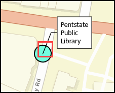
In ArcGIS Pro, leader lines can be added to labels in a point feature class using callouts. However, the leader lines are anchored to the center of the point marker symbols by default. As a result, a portion of the leader lines overlap or cover the marker symbols on the map, as shown in the image below.
This article provides two workflows to prevent label leader lines from overlapping marker symbols in ArcGIS Pro.
Procedure
Note:
These workflows do not work for labels with the balloon callout.
Prevent label leader lines from overlapping marker symbols by applying the Cut effect
- Open the ArcGIS Pro project.
- In the Contents pane, right-click the feature class > Labeling Properties… to open the Label Class pane.
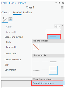
- In the Label Class pane, on the Symbol tab, expand Callout.
- Click the Leader line symbol drop-down arrow > Format line symbol….

- Apply the Cut effect to the leader line.
- In the Format Embedded Line Symbol subpane, click Structure
 .
. - Under Layers, browse to the leader line layer and click Add effect > Cut.
- In the Format Embedded Line Symbol subpane, click Structure
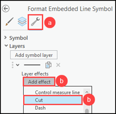
- Click the Layers
 icon and expand Cut effect.
 - Increase the Begin cut value until the leader line does not overlap the marker symbol and click Apply.

Note:
Increase the End cut value to cut the other end of the leader line if required.
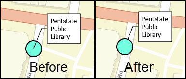
The image below shows the label leader line and marker symbol before and after the Cut effect is applied.
Prevent label leader lines from overlapping marker symbols by adding a new marker symbol to the end of the leader line
- Open the ArcGIS Pro project.
- In the Contents pane, right-click the feature class > Labeling Properties… to open the Label Class pane.
- In the Label Class pane, on the Symbol tab, expand Callout.
- Click the Leader line symbol drop-down arrow > Format line symbol….
- Add a marker symbol to the end of the leader line.
- In the Format Embedded Line Symbol subpane, click Structure
 .
. - Under Layers, click Add symbol layer > Marker layer.
- In the Format Embedded Line Symbol subpane, click Structure
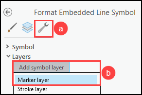
- Style the new marker symbol layer.
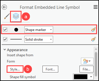
- Click Layers
 and select the new marker symbol layer.
 - Under Appearance, click Style... to open the Choose a shape window.
- Click Layers
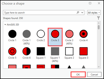
- In the Choose a shape window, select the desired shape, and click OK. In this example, Circle 3 is selected.
- In the Label Class pane, under Appearance, increase the Point size value until the leader line marker symbol conceals the point feature class marker symbol.
- Configure any remaining text symbol properties of the leader line marker symbol as desired, such as color, and click Apply.
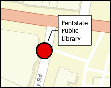
The image below shows the new leader line marker symbol concealing the original point feature class marker symbol.
Article ID: 000031372
- ArcGIS Pro 3 1
- ArcGIS Pro 3 0
- ArcGIS Pro 2 9x
Get support with AI
Resolve your issue quickly with the Esri Support AI Chatbot.


Related Information
Discover more on this topic
Search for related information
Find training related to this topic
Explore ideas and give feedback
Get help from ArcGIS experts
Start chatting now