HOW TO
Determine bearing for line features in ArcGIS Pro
Summary
Bearing is a directional measurement used to describe the orientation of a line relative to north or south, commonly expressed in a quadrant bearing format, such as N 45° E. Bearings provide precise directional information for linear features, which helps support consistent interpretation of linear feature orientation and spatial relationships. This article describes the workflow to determine bearing for line features in ArcGIS Pro.
Procedure
Use the Distance and Direction tool
Note:
This method presents the bearing as an angular measurement instead of using the quadrant format.
Use the Distance and Direction tool to create new lines interactively on top of the existing features to measure their angles. Refer to ArcGIS Pro: Create lines interactively for instructions.
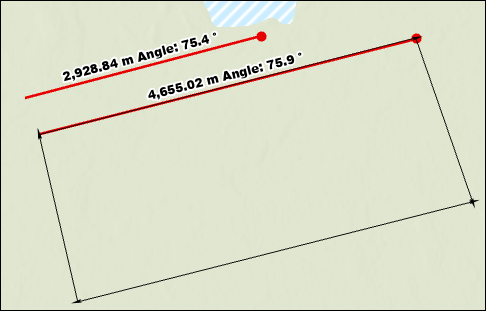
The image below shows the newly created lines with bearing and distance values displayed on the map.
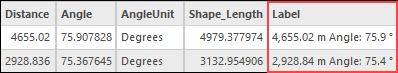
The image below shows the attribute table displaying the distance and bearing values in the Label field.
Use the Measure Direction Distance tool
Use the Measure Direction Distance tool to measure the bearing of features in a quadrant format. Refer to ArcGIS Pro: Measure in a map or scene for instructions. When features are measured, the bearing values are displayed in the Measure Direction Distance window but are not automatically saved to the attribute table. To retain the values, click Copy Results  or manually copy and paste them into the attribute table. Alternatively, use the Measure Distance tool to measure bearing as an angular measurement.
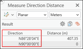
The image below shows the measured bearing value displayed in the Measure Direction Distance window.
Use the Traverse tool
Use the Traverse tool to trace the existing features and measure their bearing. Refer to ArcGIS Pro: Trace traverse lines for instructions. Enable COGO before using the Traverse tool to save the bearing values automatically. If COGO is not enabled, the bearing values are displayed in the Traverse pane but are not saved automatically to the attribute table. In this case, manually copy and paste the values into the attribute table.
The image below shows the bearing values displayed in the Traverse pane.

Use the Calculate Geometry Attributes tool
Use the Calculate Geometry Attributes tool to calculate the line bearing in a north azimuth or quadrant format. This method requires the X and Y coordinates of the line's start and end positions. Refer to How To: Batch calculate line directions from north azimuth to quadrant bearing in ArcGIS Pro for instructions.
Article ID: 000039552
- ArcGIS Pro
Get support with AI
Resolve your issue quickly with the Esri Support AI Chatbot.


Related Information
Discover more on this topic
Search for related information
Find training related to this topic
Explore ideas and give feedback
Get help from ArcGIS experts
Start chatting now