HOW TO
Identify the spatial reference, projection, or coordinate system of data
Summary
GIS and Computer Aided Design (CAD) data are frequently received with no spatial reference information. ArcMap's 'project on-the-fly' utility requires that projections be defined so that the data aligns in ArcMap. Therefore, the coordinate system of the data must be identified and defined.
The instructions provided describe how to identify the spatial reference, projection, or coordinate system of data.
Note:
Refer to FAQ: Projection Basics: What the GIS professional needs to know for more information before proceeding.
Procedure
Data can be created in one of three types of coordinate systems:
- Geographic
- Projected
- Local
To identify the correct coordinate system, examine the extent of the dataset. Determine which type of coordinate system best matches the dataset's extent information, and visit the related article for that specific type of coordinate system.
- Examine the coordinate extent of the dataset.
- Start ArcMap with a new, empty map.
- Click the Add Data button, and add the data with the unknown coordinate system to ArcMap.
- Right-click the name of the layer, click Properties, and select the Source tab.
- In the Extent section, note the number of digits to the left of the decimal on the top, bottom, left, and right positions.
- Include the minus (-) sign if the coordinates are negative.
- Ignore any digits to the right of the decimal.
- Save this information for comparison against the properties of Geographic, Projected, and Local coordinate systems as listed below.
- Determine which type of coordinate system best matches the dataset's extent information.
Geographic Coordinate Systems
Geographic coordinate systems (GCS) use units of decimal degrees for coordinates. These units are often referred to as 'lat' and 'long'.
Decimal degrees (DD) are angles, and these units of measure are often used with GIS data but rarely with CAD data.
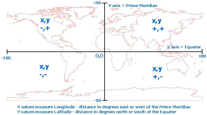
There are 360 degrees in a circle, so coordinates in DD can never be over three digits to the left of the decimal. X-coordinates are longitude values. For data in North America, the longitude values must be negative numbers between 0 and -180. Y-coordinates are latitude values. For data in North America, the latitude values must be positive numbers between 0 and +90.
The graphic below shows the distribution of positive and negative values for longitude (X) and latitude (Y) coordinates worldwide.
Data with coordinates in decimal degrees are in a GCS. These data can be created on a vast number of different datums. The most commonly used datums in North America are North American Datum 1927 (NAD 1927), North American Datum 1983 (NAD 1983), and World Geodetic Survey 1984 (WGS 1984). To define the coordinate system for data in a geographic coordinate system, the correct GCS must be selected.
Note:
Refer to FAQ: What do the terms geoid, ellipsoid, spheroid and datum mean, and how are they related? for more information about datums.
If the dataset's extent information appears to belong to a geographic coordinate system, refer to FAQ: What geographic coordinate system or datum should be used for my data? for more information.
Projected Coordinate Systems
Both GIS and CAD data can be created using projected coordinate systems (PCS). A wide variety of predefined projected coordinate systems, using different units and datums, are installed with ArcGIS. In the United States, the most commonly used projected coordinate systems are State Plane and Universal Transverse Mercator (UTM).
Most often, data projected to these coordinate systems have an extent with six to eight digits to the left of the decimal.
If the dataset's extent information appears to belong to a projected coordinate system, refer to the relevant articles below for the user's version of ArcGIS Desktop:
- How To: Identify an unknown projected coordinate system using ArcMap.
- ArcMap: Identifying an unknown coordinate system
If using ArcGIS Desktop 10.1, 10.2.x, or 10.3.x, refer to How To: Create a custom projection file to align CAD Data in ArcMap 10.1 and above.
Local Coordinate Systems
CAD data is frequently created in a local coordinate system.
Unlike data in a geographic coordinate system that has its origin (0,0 coordinates), where the Prime Meridian crosses the Equator off the west coast of Africa, a local coordinate system can have its origin (0,0) anywhere on the surface of the earth.
When the extent of a dataset has three to five digits to the left of the decimal, it is most likely in a local coordinate system.
Note:
CAD data in a local coordinate system can be aligned with other data in a projected coordinate system in ArcMap by creating a custom projection file.
If the dataset's extent information appears to belong to a local coordinate system, refer to How To: Create a custom projection file in ArcMap to align CAD data .
Article ID: 000007880
- ArcMap
Get support with AI
Resolve your issue quickly with the Esri Support AI Chatbot.


Related Information
Discover more on this topic
Search for related information
Find training related to this topic
Explore ideas and give feedback
Get help from ArcGIS experts
Start chatting now